Three-dimensional Manipulation of Hydrogel Microparticles by Positional Change of Light Focus in Stop Flow Lithography
ABSTRACT
Hydrogel microparticles have garnered substantial attention in the fields of drug delivery, tissue engineering, and biosensing due to their properties of high biocompatibility, hydrophilicity, and tunability. Stop flow lithography (SFL), a microfluidic-based photopolymerization technique, has emerged as one of the leading methods by which these particles are synthesized due to its high throughput of controlled geometrically defined particles and ease of use. Previous research assumes that light distributes evenly throughout the SFL flow channel due to the almost instantaneous speed of light (3*108 m/s), synthesizing uniformly shaped hydrogels. In this study, the position of UV-light focus in SFL was manipulated using microscope focus, to which three-dimensional differences in hydrogel shapes were observed, disproving this presumption and ultimately suggesting that light intensity is not uniformly distributed. In observing these three-dimensional differences, we also discovered a technique by which SFL, normally confined to two-dimensional control, can be used to manipulate three-dimensional hydrogel shape. Furthermore, we explored potential applications of this technique in the fields of multiplex immunoassays, tissue engineering, and drug delivery. Our results indicate that the ability to manipulate hydrogels in a three-dimensional manner significantly enhanced all three fields, demonstrating promising application of this technique in biomedical and clinical fields.
INTRODUCTION.
The three-dimensional shape of hydrogel microparticles plays a central role in determining functional performance in biomedical applications such as drug delivery [1], tissue engineering [2-4], and immunoassays [5]. Advances in microfabrication technologies have enabled significant progress in the ability to control the three-dimensional shape of hydrogel microparticles. Specifically, micromolding techniques [6], 3D printing [7], and self-assembly [8] have allowed for the precise fabrication of hydrogel particles with intricate shapes and structural features. However, although these methods provide a means to control 3D hydrogel shape, their main pitfalls are the difficulties in producing diverse distinct hydrogel shapes at a high throughput [10].
This paper explores three-dimensional manipulation of hydrogels synthesized using Stop Flow Lithography (SFL), a technique traditionally limited to two-dimensional control of hydrogel shape. SFL is a microfluidic photopolymerization-based particle synthesis technique, which is highly automated and has an extremely high throughput. In this technique, a precursor flows at laminar flow velocity through a microfluidic channel before it is stopped and UV light is projected through a photomask. The areas of precursor exposed to UV light initiate a photopolymerization reaction, solidifying the precursor into a distinct shape based on the photomask pattern. The flow is subsequently restarted until the particle moves out of the UV lens’s view, at which point the flow is once again stopped, and the process is repeated [11]. Although SFL currently controls two-dimensional shape by use of a photomask directing UV light in specific patterns, three-dimensional manipulation is not controlled. In this paper, we investigate how changing the vertical position of UV light microscope focus in the SFL channel for the polymerization process affects the three-dimensional shapes of the particles and test the practical applications of these particles through fluorescence marking and a mathematical analysis of the hydrogels.
Additionally, in SFL, one of the main assumptions is that the polymerization process occurs instantaneously. This assumption stems from the presumption that light, which initiates the polymerization reaction, travels so fast (3*108 m/s) that it is uniformly distributed across the reaction channel, ensuring an instantaneous even crosslinking of the polymer network and hence uniform particle structure [11-12]. By investigating how the position of light focus changes the shape and uniformity of the hydrogels, this paper also challenges this common assumption that light distribution and the polymerization reaction are instantaneous and uniform.
MATERIALS AND METHODS.
Synthesis of Hydrogels.
All materials were purchased from Sigma-Aldrich. Details of the fabrication of the SFL device are outlined in supporting information. A precursor solution of 40 µL poly(ethylene glycol) diacrylate (MW = 700 Da), 80 µL poly(ethylene glycol) (PEG 600 MW = 600 Da), 70 µL deionized water, and 10 µL of Darocur 1173 was delivered into the SFL device via a modified pipette. Tubing was connected to the pipette which controlled air flow. Particles were fabricated in cyclical manner, each cycle consisting of flow (400 ms), stop (300 ms), UV-exposure (40 ms), and hold (240 ms). UV intensity was controlled at 5 mW/cm2 and the pressure of the open valve during the flow step was controlled at 20 kPa. Depending on the desired horizontal particle shape, different photomasks were also used.
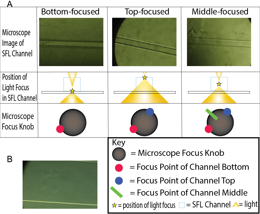
The objective of this experiment was to observe how the different position of UV-light focus affects particle shape. Therefore, we tested 2 main microscope focus positions: the bottom of the channel height and the middle of the channel height. The bottom and top were easily identifiable as the channel edges were crisp and solid under the microscope when light was focused at the bottom and top of the channel. To find the middle of the channel height, we introduced a robust yet sufficient technique. Because the bottom and top of the channel were easily identified visually, both points were marked on the focus knob of the microscope using tape. By marking the midpoint between these two points in the microscope focus knob, we found a satisfactory focus position which approximately focused light at the center of the channel height (Fig. 1A).

For each batch of particles or trial, 4,000-16,000 hydrogels were synthesized. We conducted trials for bottom-focused light synthesized hydrogels, hydrogels printed with UV light focused at the bottom of the channel, and middle-focused light synthesized hydrogels, hydrogels printed with UV light focused at the middle of the channel. Both these trials were also conducted for triangular and circular photomasks. Each batch of particles was extracted from the device outlet with PEG 200 and rinsed 3 times with phosphate-buffered saline with Tween 20 (PBST) to remove unreacted precursor. 10 µL of rinsed solution was studied under a light microscope and particles were photographed. The sample print hydrogels (Fig. 1B) were in an upright position as they had just been synthesized and hence appeared different from the collapsed hydrogels (Fig 2A, Fig 2B).

Fluorescein PEG Thiol (FITC-PEG-SH) Conjugation.
For Fluorescein PEG Thiol (FITC-PEG-SH) Conjugation, 99 µL of hydrogel particles suspended in the PBST and 1 µL of FITC-PEG-SH (1 mg/mL) were added together in a microtube. Both hydrogels synthesized via bottom-focused light and middle-focused light were used. Microtubes were subsequently added to a “Thermo-Shaker” which ran for 19 hours at 1500 RPM at 37 °C. Through this process, the thiol-ene reaction was initiated and completed. Post “thermo-shaking”, the particles were rinsed 3 times in PBST and were fluorescently photographed with a fluorescence exposure time of 80 ms and 2×2 binning. Fluorescence signals of each photographed particle were recorded.
RESULTS.
Effect of Light Focus on Three-Dimensional Particle Uniformity.
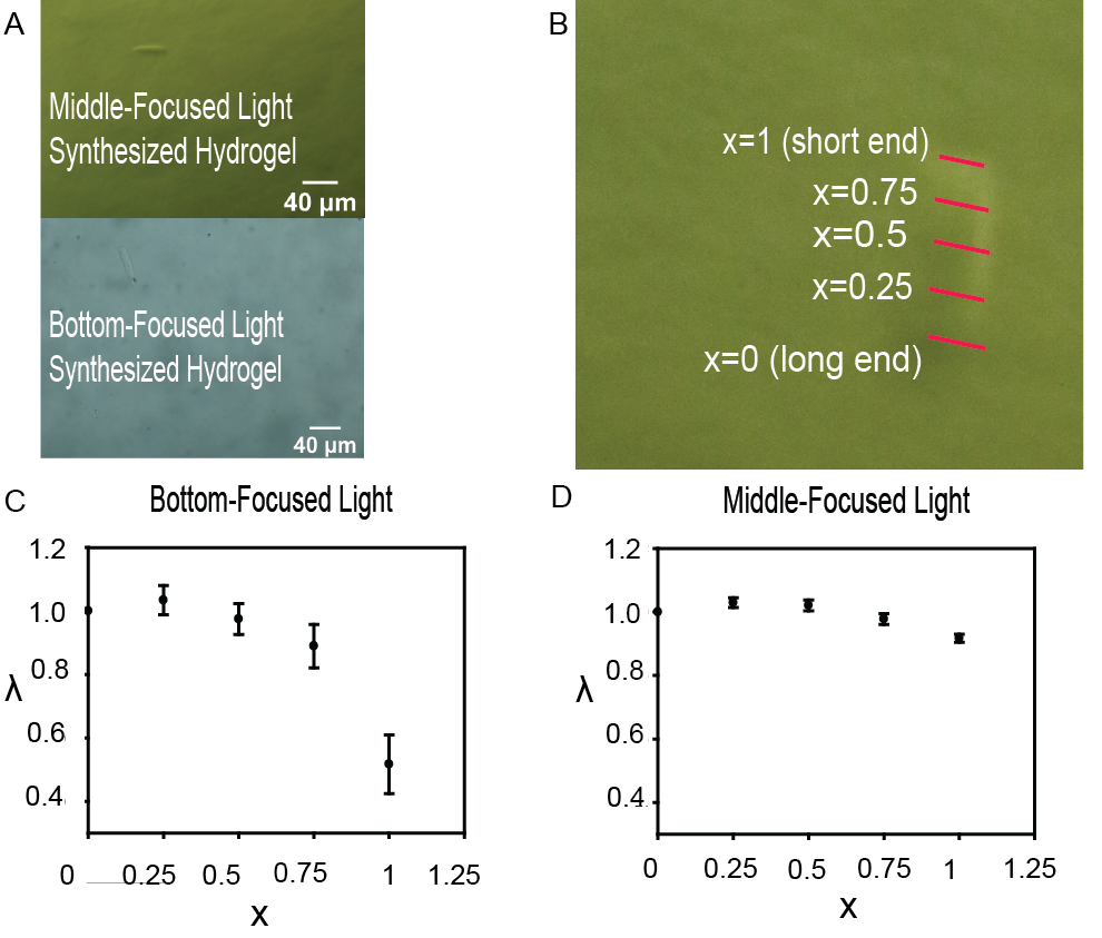
The photographed hydrogels demonstrated a clear difference in shape between hydrogels produced via middle-focused light and bottom-focused light (Fig. 2A). Uniformity was defined by evenness in the width of the collapsed hydrogel, observed from the hydrogel’s lateral plane (Fig. 2B). Due to synthesis in a deep flow channel (100 µm), the hydrogels also had a high height aspect ratio, making them mechanically unstable. As a result, they collapsed before being analyzed on a glass slide, appearing in lateral orientation in the images. Middle-focused light synthesized hydrogels showed much clearer uniformity in shape compared to bottom-focused light synthesized hydrogels, which were more trapezoidal. To compare uniformity between particles quantitatively, we devised a metric for comparison. This involved measuring five equidistant horizontal widths across the vertical axis of the collapsed hydrogel, with initial position x = 0 always representing the position of the longer end of the hydrogel, and x = 0.25, x = 0.5, x = 0.75, and x = 1 (the shorter end of the hydrogel) referring to the respective adjacent positions (Fig. 2B). A unit x was used because channel height was not consistent for each PDMS device, likely due to differing degrees of capillary action of partially cured PDMS along the SFL channel, leading to inconsistent hydrogel height, therefore necessitating a dimensionless unit of position for comparing hydrogels. Although width was measured on ImageJ in µm, the metric in question is change in uniformity. Therefore, a unit demonstrating sole changes in width throughout the hydrogel is preferable for comparing the bottom-focused light synthesized particles to middle-focused light synthesized particles. We introduce a nondimensional λ to represent the change in width throughout the hydrogel as a ratio of hydrogel width at a point x = a to the width at initial point x = 0,
\[\lambda_{x=a}=\frac{w_{x=a}}{w_{x=0}}\tag{1}\]
where w is width, is the λ at position x = a, is the width at position x = a, and is the width at position x = 0. λ values were recorded for each position, x, of each photographed bottom-focused light synthesized hydrogel (n = 88) and middle-focused light synthesized hydrogel (n = 74).
For establishing a difference between the middle-focused and bottom-focused distributions, 95% confidence two sample t-tests were used, comparing λ between the middle-focused and bottom-focused light groups with this significance test for each position, x = 0, x = 0.25, x = 0.5, x = 0.75, and x = 1 (Fig. 2C, Fig. 2D). The null hypothesis (H0) is when the difference between bottom-focused light λ and middle-focused light λ at a point x is 0. The alternate hypothesis (HA) is when the difference is not 0. Conditions for this test were satisfied as samples were randomized via vortexing, samples were independent as both groups were separately synthesized in different batches with appropriate treatments, and the central limit theorem was satisfied (number of samples exceeds 30 for both groups). The tests, based on α = 0.05, indicated a statistically significant difference between the middle-focused and bottom-focused groups for positions x = 0.8 (p = 0.0236) and x = 1 (p = 1.252*10-11), hence rejecting the null hypothesis. Therefore, we are 95% confident that the hydrogel at points x = 0.75 and x = 1 were different in width for middle-focused light synthesized particles and bottom-focused light synthesized particles, and that the position of light focus does indeed alter three-dimensional particle shape. Upon further graphical analysis (Fig. 2C, Fig. 2D), it is clear that particles synthesized via middle-focused light were much more uniform, with λ values closer to 1 and greater than the low λ values in the particles synthesized by bottom-focused light at x = 0.75 and x = 1 to a statistically significant extent. Therefore, we can conclude that the position of light focus manipulates the three-dimensional shape of synthesized hydrogels.
Application of Shape Manipulation for Multiplex Immunoassays.
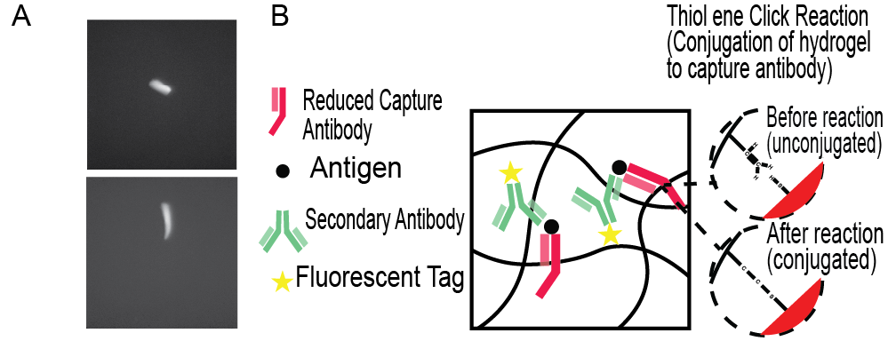
The light focus manipulated hydrogels demonstrated a very clear fluorescence signal (Fig. 3A). Conducting a one-sided t test can statistically confirm the significance of the fluorescence signal, where H0 is fluorescence signal being 0 and HA is the fluorescence signal being greater than 0. Conditions required for a t-test were satisfied, as samples were randomized via vortexing, samples were independent, and the central limit theorem was satisfied (n = 31 > 30). The calculated p value was 1.1442*10-10, which at α = 10-9, signified a rejection of the null hypothesis. Therefore, we are ~100% confident that these hydrogel microparticles emitted a fluorescence signal. In establishing that these hydrogel microparticles emitted fluorescence, the binding of FITC-PEG-SH to the unreacted double bonds in the hydrogel matrix through the thiol-ene-click reaction is also confirmed. Hence, it can be assumed that reduced capture antibodies are capable of bonding to these hydrogels through the same thiol-ene-click reaction. Graphically encoded hydrogel-based assays rely upon the binding of reduced capture antibodies to the hydrogel matrix via the thiol-ene click reaction, which are in turn bonded to target antigens joined to fluorescently labeled secondary antibodies, essentially connecting all components to the hydrogel (Fig. 3B) [9]. Therefore, these geometrically distinct hydrogels capable of binding to antibodies can be used in multiplex immunoassays, with their distinct shapes acting as geometric barcodes to allow for multiplexing.

Surface Area to Volume Ratio.
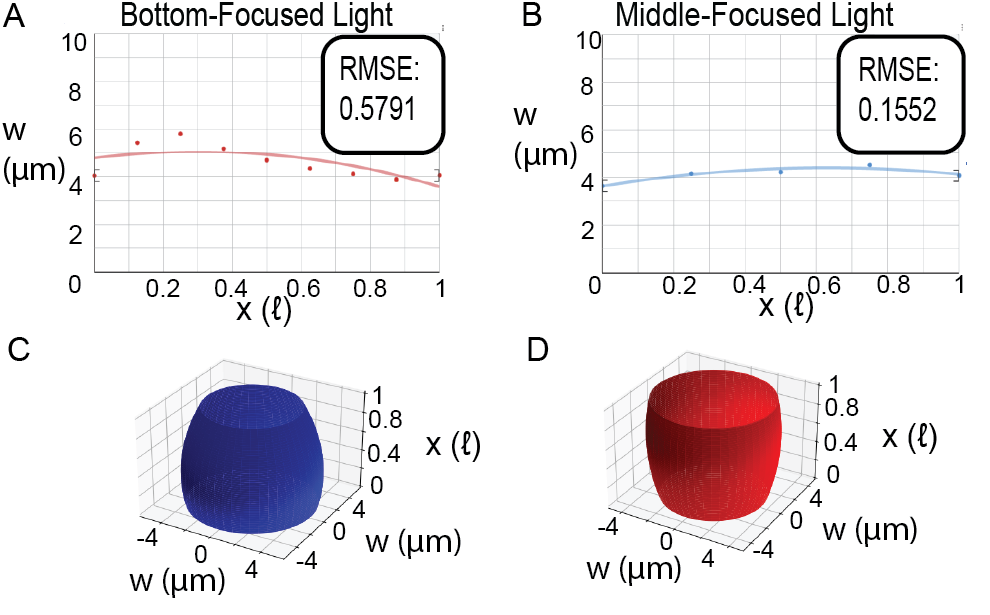
Analysis of the surface area to volume ratio utilized hydrogels synthesized with the circle filter (Fig. 2A), comparing middle-focused light synthesized hydrogels with the bottom-focused light synthesized hydrogel. Our approach utilized a regression-based mathematical model of the hydrogels and calculus to calculate and compare the surface area to volume ratios. For developing the mathematical model, a similar methodology to the aforementioned particle uniformity analysis was used. However, for this method, widths across the vertical axis of the collapsed hydrogel were measured in μm and divided by 2 (the regression graph models half the two-dimensional view of the particle (Fig. 2A) divided by the hydrogel’s central axis of symmetry), with initial position x = 0ℓ, in which ℓ is the variable length of the hydrogel, always representing the position of one end of the hydrogel, and x = 0.125ℓ, x = 0.25ℓ, x = 0.375ℓ, x = 0.5ℓ, x = 0.625ℓ, x = 0.75ℓ, x = 0.875ℓ, and x = 1ℓ (the other end of the hydrogel) referring to the respective adjacent positions (Fig. 2B for reference). Conducting a regression analysis using Vernier Graphical Analysis (Fig. 4A, Fig. 4B), the following two equations modeled the shape of half the hydrogel for both bottom-focused light and middle-focused light synthesized hydrogels, where w is hydrogel width.
\[w_{\mathrm{bottom}}=-2.996x^2+1.803x+4.784 \tag{2}\]
\[w_{\mathrm{middle}}=-1.909x^2+2.401x+3.62\tag{3}\]

Next, these two-dimensional models were converted to three-dimensional representations of the synthesized hydrogels. Since it is assumed that the hydrogel shape is symmetric about its central axis a three-dimensional model was derived by rotating the width functions about the x-axis (Fig. 4C, Fig. 4D). Given this three-dimensional model, the volumes (V) and surface areas (SA) of both hydrogels were calculated.
\[V_{\mathrm{bottom}}=\pi\int_{0}^{1}\left(w_{bottom}\right)^2 dx\approx69.539\ \mu m^2\tag{4}\]
\[V_{\mathrm{middle}}=\pi\int_{0}^{1}\left(w_{middle}\right)^2 dx\approx55.128\ \mu m^2 \tag{5}\]
\[SA_{\mathrm{bottom}}=2\pi\int_{0}^{1}{w_{bottom}\sqrt{1+\left(\frac{d}{dx}w_{bottom}\right)^2}dx}\approx59.534\ \mu m\tag{6}\]
\[SA_{\mathrm{middle}}=2\pi\int_{0}^{1}{w_{\mathrm{middle}}\sqrt{1+\left(\frac{d}{dx}w_{\mathrm{middle}}\right)^2}dx}\approx38.889\ \mu\ m\tag{7}\]
Subsequently, the surface area to volume ratio was calculated for each hydrogel.
\[\frac{SA_{\mathrm{bottom}}}{V_{\mathrm{bottom}}}\approx0.856\ \mu m^{-1} \tag{8}\]
\[\frac{SA_{\mathrm{middle}}}{V_{\mathrm{middle}}}\approx0.705\ \mu m^{-1}\tag{9}\]
Analyzing the results, it was observed that the bottom-focused light synthesized hydrogels had a surface area to volume ratio 21.42% greater than the middle-focused light synthesized hydrogels.
DISCUSSION.
In this study, we developed a method by which UV light focus can be controlled in the stop flow lithography process to manipulate the three-dimensional shape of synthesized hydrogels. In demonstrating that changes in light position affect particle shape, the notion that light travels so fast that it distributes evenly across the SFL channel and initiates the polymerization reaction instantaneously and uniformly is disproven. Additionally, we successfully binded these three-dimensionally distinct hydrogels to FITC-PEG-SH in the thiol-ene click reaction, emulating the process of binding to capture antibodies in multiplex immunoassays. This revealed the application of our focus-based technique of producing three-dimensionally manipulated hydrogels for conducting code-based multiplex immunoassays without the need for using multiple cost-prohibitive photomasks. Finally, we developed three-dimensional mathematical models for our two distinct hydrogels, calculating the surface area to volume ratios of both. In finding that hydrogels with bottom-focused light had a larger surface area to volume ratio than middle-focused light, we highlight the application of our focus-based three-dimensional manipulation technique in maximizing surface area to volume ratio, which is especially beneficial for designing optimal tissue engineering and drug delivery hydrogels as a larger surface area to volume ratio maximizes nutrient diffusion and release kinetics.
Several limitations of this paper must be acknowledged. Most notable are variations in channel height throughout different SFL devices. Due to differing degrees of capillary action dragging partially cured PDMS of the slide glass into the PDMS device, and hence the SFL channel, channel heights varied in devices. As a result, hydrogels, which have heights heavily dependent on channel height, had varying heights. In order to make this technique more practicable and implementable, hydrogel height must also be consistent, as techniques like multiplex immunoassays rely on easy identifiability of particles with consistent geometric shapes [14]. The most straightforward solution to this problem would be to increase the channel width, minimizing capillary action, hence decreasing variation in hydrogel heights. Additionally, the robust technique by which light was focused at the center of the channel (Fig. 1A), while serving this paper’s purposes, can be improved. If this middle focus point is found digitally or by a computer in a calculated precise manner, particles will be even more uniform, making the difference between middle-focused light synthesized particles and bottom-focused light synthesized particles even more pronounced.
Future research exploring this technique is also necessary. While the FITC-PEG-SH simulation done in this report does confirm that these hydrogels will work in the context of multiplex immunoassays, conducting actual immunoassays with these particles with either controlled or clinical samples will reveal the true practicality and effectiveness of these three-dimensionally distinct hydrogels. In regard to the application of these hydrogels in the context of tissue engineering and drug delivery, similar experiments must be conducted. Factors like encapsulation efficiency and biodegradability must be explored to proceed to in vivo applications. While many more experiments will be necessary to move this technique into the realm of clinical medicine, this paper takes a key step forward in the effort to further hydrogel microparticle-based clinical applications.
SUPPORTING INFORMATION.
Supporting information includes procedure and graphic outlining SFL device fabrication; Specific procedure of particle recovery, rinsing, and photography.
ACKNOWLEDGMENTS.
A special thanks to Dr. Ki Wan Bong and Wookyoung Jang at Korea University for their guidance and support.
REFERENCES.
- U.S. Madduma‐Bandarage, S.V. Madihally, Synthetic hydrogels: Synthesis, novel trends, and applications. J. Appl. Polym. Sci. 138, 50376 (2021).
- N. Annabi, et al, 25th anniversary article: Rational design and applications of hydrogels in regenerative medicine. Adv. Mater. 26, 85–124 (2014).
- Z. Wei, et al, Microfluidics fabrication of micrometer‐sized hydrogels with precisely controlled geometries for biomedical applications. Adv. Healthc. Mater. 11, 2200846 (2022).
- G. Réthoré, A. Pandit, Use of templates to fabricate nanoscale spherical structures for defined architectural control. Small 6, 488–498 (2010).
- J. Kim, et al, The detection of urinary exosomal miRNAs for cancer diagnostics and prognostics. BioChip J. 17, 308–317 (2023).
- H.U. Kim, Y.H. Roh, S.J. Mun, K.W. Bong, Discontinuous dewetting in a degassed mold for fabrication of homogeneous polymeric microparticles. ACS Appl. Mater. Interfaces 12, 53318–53327 (2020).
- F. Xu, et al, Hydrogels for tissue engineering: addressing key design needs toward clinical translation. Front. Bioeng. Biotechnol. 10, 849831 (2022).
- S.J. Jeon, A.W. Hauser, R.C. Hayward, Shape-morphing materials from stimuli-responsive hydrogel hybrids. Acc. Chem. Res. 50, 161–169 (2017).
- W. Jang, E.L. Song, S.J. Mun, K.W. Bong, Efficient isolation of encoded microparticles in a degassed micromold for highly sensitive and multiplex immunoassay with signal amplification. Biosens. Bioelectron. 116, 465 (2024).
- Z.L. Wu, et al, Three-dimensional shape transformations of hydrogel sheets induced by small-scale modulation of internal stresses. Nat. Commun. 4, 1586 (2013).
- D. Dendukuri, et al, Stop-flow lithography in a microfluidic device. Lab Chip 7, 818–828 (2007).
- D. Dendukuri, et al, Modeling of oxygen-inhibited free radical photopolymerization in a PDMS microfluidic device. Macromolecules 41, 8547–8556 (2008).
- D. Dendukuri, et al, Continuous-flow lithography for high-throughput microparticle synthesis. Nat. Mater. 5, 365–369 (2006).
- J.H. Choi, W. Jang, Y.J. Lim, S.J. Mun, K.W. Bong, Highly flexible deep-learning-based automatic analysis for graphically encoded hydrogel microparticles. ACS Sens. 8, 3158–3166 (2023).
- Y.H. Roh, et al, Direct conjugation of streptavidin to encoded hydrogel microparticles for multiplex biomolecule detection with rapid probe-set modification. Polymers 12, 546 (2020).
- H.J. Lee, et al, Linker-free antibody conjugation for sensitive hydrogel microparticle-based multiplex immunoassay. Analyst 144, 6712–6720 (2019).
Posted by buchanle on Friday, June 20, 2025 in May 2025.
Tags: Biomedical Applications, Hydrogels, Polymers

