Preliminary Results of Studying the Effects of the Xbox Kinect on Indoor Autonomous Exploration Robots: A Case Study
ABSTRACT
Robotics in secondary education is vital in developing a modern workforce; however, many US schools lack the resources to offer such opportunities. This study explores the impact of integrating an Xbox Kinect into a two-dimensional indoor exploration autonomous robot in a cost-effective way. It showcases a potential method for reducing computational costs while advancing robotics education for financially restricted institutions by operating a robot with widely available processors.
INTRODUCTION.
Robotics education in secondary schools holds potential in producing “qualified workers in the science, technology, engineering and mathematics (STEM) fields” and solving “lack of academic preparation in middle and high school” [1]. Furthermore, competitive robotics programs such as the FIRST Robotics Competition significantly increases students’ attitudes towards science [2]. Anecdotally, there is something to be said about Havelock High School’s engineering education; numerous students have seen postsecondary success at the North Carolina State University School of Engineering, and Havelock’s engineering classroom is littered with students’ inventions. Over the past few years, the engineering teacher, Mr. John Scarfpin, has unsuccessfully posed a project to his most successful students: the reverse engineering of a donated electric wheelchair. The difficulty of this project stands in the lack of available resources, specifically in both the reverse engineering and the control structure. As the researcher of this study, I created the objective of identifying an affordable solution to this long-standing project (Figure 1).

Despite projections of there being 20 million robots worldwide by 2030, many students do not have access to a robotics education [3]. In select documentations on the integration of robotics into secondary education, universities played an important role. Wedeward et al. utilized resources from New Mexico Tech as they produced robotics kits for high school engineering programs in the surrounding area [4]. Verner et al. accomplished the same with MIT [5]. Despite the engagement of these educational institutions, many high schools across the country do not have access to university collaboration. Providing an alternative and additional to the support of colleges and universities for high school robotics has been a standing goal for Havelock High School’s engineering department and is a purpose of this study.
The primary objective of this study was the development of a robot that possesses the capability to autonomously navigate and deliver packages throughout Havelock High School while effectively avoiding obstacles that may go undetected by two-dimensional map, like those made by the two-dimensional Light Detection and Ranging (LiDAR) system–which, unlike its three-dimensional counterpart, can only produce a singular horizontal plane of data. To achieve this objective, the research focused on leveraging three-dimensional data offered by the Xbox Kinect–a popular camera for the video game console. Specifically, this study delved into the application of Xbox Kinect in a two-dimensional costmap–a map of the “cost,” or the likelihood to crash, for each measured point–configuration primarily driven by the need to address the computing difficulties associated with more complex three-dimensional mapping and navigation systems. By investigating the integration of Xbox Kinect into the robot’s framework, this research aimed to unlock new possibilities for enhancing obstacle avoidance and creating a more efficient and reliable autonomous delivery robot. Overall, this research aims to provide insights into a method for reducing costs while advancing robotics education for programs and institutions with financial limitations.
METHODS.
The robot was constructed using an Invacare Sure Step M91 Pronto electric wheelchair, two twelve-volt deep cycle car batteries, Raspberry Pi 4B, Ld14 LiDAR, two Arduino Unos, two IBT_2 motor drivers, twelve neodymium magnets, two Redboard hall effect sensors, MPU6050, and an Xbox 360 Kinect.
Software Optimization.
To overcome processing limitations, a carefully configured Ubuntu 20.04 kernel was implemented on the Raspberry Pi 4B, utilizing Ubuntu Mate and the SLiM GUI manager. ROS Noetic was downloaded to provide robotics assistance, and a RealVNC server facilitated remote control from laptops or mobile devices.
The Raspberry Pi downloaded a GUI-less and netplan-less Ubuntu 20.04 64-bit kernel to optimize the allocation of resources. By doing so, the developer could eliminate unnecessary components to allow the robot’s software to prioritize essential tasks. The netplan was configured to only recognize the home and school networks. Subsequently, the researcher downloaded SLiM manager to run the Ubuntu Mate GUI, ensuring maximum resources are available for critical operations like path planning and mapping algorithms.
ROS Noetic [6] was downloaded from ROS.org to produce an efficient robot design and enhance the developer’s understanding of complex concepts. The developer leveraged the freenect_stack package to harness the full potential of the Xbox Kinect. During early development, the developer gained insight to the usage of freenect_stack within real-time appearance-based (RTAB) maps, which ultimately led to the creation of a method applicable to a two-dimensional costmap. Recognizing the limitations of the robot’s odometry with only 5.3 ticks per meter, the developer incorporated the hector_slam package. This package provided accurate ICP data for localization within the procedurally generated map, surpassing the resolution of the wheel odometry used in conventional packages like gmapping. To address inefficiencies and prevent sudden pose changes due to errors, the developer introduced the robot_pose_ekf, which combined the IMU data with wheel odometry to provide continuous information between ticks and allow for a comparison of the two systems.
The RealVNC Server was obtained from the Raspberry Pi download page on the RealVNC website. Its purpose was to enable real-time monitoring and configuration of the robot while it was in motion and generating data. Using an HDMI display for monitoring would have been inconvenient and inefficient in this context.
Mobile Base Design.
The base of the robot consisted of a M91 electric wheelchair with functioning motors. The wheelchair provided the foundation for the robot’s base link, allowing a 3D printed cover to incorporate the necessary electronics and sensors. Twelve-volt deep cycle batteries powered the electronics, while a power array distributed power within the robot. A step-down module maintained proper voltage between the Raspberry Pi and the power array. Please note that, for safety and financial reasons, the robot was tethered by a power cord for most of the design process.
Due to budget limitations, various parts were sourced from different kits and previous projects to develop the robot. The M91 electric wheelchair was generously donated to our school’s engineering program, providing a free pair of motors and stable base for the robot’s development. Since the design process of others who had worked on similar projects was loosely documented, it was necessary to search through unconventional sources for information on how to modify this specific wheelchair. The motors in the wheelchair have four pins: the middle two serve as electric brake pins, which are only active when the wheelchair is in drive mode, while the outer two function as the conventional motor’s positive and negative pins. According to the downloadable documentation, the wheelchair operates on a 24-volt system to power its motors. However, for safety reasons and to prevent potential harm or damage, the developer opted to utilize only half of this voltage to reduce the excessive speed of the wheelchair. These motor pins were connected to the IBT_2 motor drivers, which were connected to the base controller Arduino.
Localization Development.
The robot utilized the robot_pose_ekf package in ROS, combining IMU data and odometry data for pose estimation. Odometry data was obtained by attaching magnets to the wheels’ rims and using hall effect sensors. IMU data was obtained from an MPU6050 connected to an Arduino.
The odometry data for the wheel ticks was obtained from hall effect sensors that detected the magnetic fields of 5 magnets, generating a tick for each field detected. The base controller of the robot gathered these ticks to determine the number of ticks in the positive direction. However, it’s important to note that the Arduino was not responsible for publishing the odometry. Instead, the Raspberry Pi was utilized to generate Quaternion-formatted odometry using the published wheel encoder ticks. This odometry information was then utilized by the robot in conjunction with the robot_pose_ekf package.
The second Arduino was responsible for collecting IMU (Inertial Measurement Unit) data using interrupts generated by the MPU6050 sensor. To ensure accurate readings, a calibration program was initially used to determine the exact offsets of the MPU6050. Subsequently, the MPU6050_serial_to_imu_data package was implemented, enabling the Arduino to transmit MPU6050 data to the Raspberry Pi. This package was chosen due to its ability to provide data faster, while the Raspberry Pi would capture “snapshots” of the data, ensuring more accurate IMU measurements in case of any latency introduced within the Raspberry Pi’s system.
Observation Source Stack.
A 3D printed sensor stack was created to hold the LiDAR and Kinect in front of the robot, enabling consistent observation data. The LiDAR utilized the ldlidar_sl_ros package to generate LaserScan messages, while the Kinect utilized the freenect_stack package to produce PointCloud2 messages.
To optimize the performance of the freenect_stack package, its launch file was customized to lower its frame rate. By utilizing the “freenect-xyz.launch” file, only essential depth information was retained, reducing the processing load on the Raspberry Pi. This configuration led to an improvement in the Raspberry Pi’s frame rate, enabling the robot to effectively utilize the Xbox Kinect as a sensor while conserving computational resources.
Mapping and Navigation.
An Arduino Uno was utilized as a PID controller, using the IBT_2 drivers to control the motors and incorporating wheel odometry for motor velocity monitoring. The hector_slam package provided accurate mapping capabilities for autonomous navigation. The keyboard_teleop_twist package enabled manual map creation, while localization used Adaptive Monte Carlo Localization (AMCL). A ROS trajectory local planner and navfn global planner were employed to navigate these maps.
The local planner was configured based on the robot’s linear velocities, as well as a minimum speed threshold to ensure that the PWM signal sent to the motors is sufficient for movement. However, the turning speeds were not considered in the configuration. This decision was made because the robot tended to overshoot its turns, preventing it from making progress towards its destination. Instead, it would spin in an attempt to align itself with the goal, causing fatal errors in navigation.
The costmaps were configured to utilize the robot’s odometry to improve the AMCL algorithm’s measurement of dead reckoning. The obstacle layer of the costmaps took into account the maximum distances of the LiDAR and the Kinect sensors, which were set at 8 meters and 3.5 meters, respectively. Additionally, the Kinect data was filtered based on the height of the obstacles. Any obstacle shorter than a centimeter was disregarded to prevent the floor from being mistakenly recognized as an obstacle. Similarly, obstacles that were at least one centimeter higher than the robot were also disregarded as they would not pose a navigation conflict.
RESULTS.
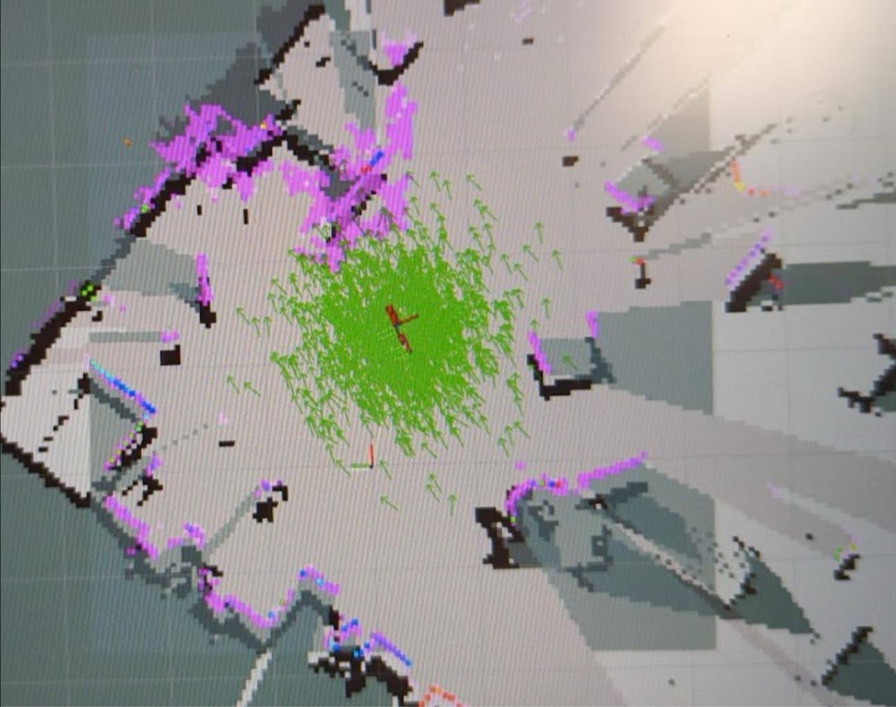
Integrating Kinect’s point cloud data into the costmaps’ obstacle layer successfully enhanced obstacle detection. The robot demonstrated improved understanding of dynamic obstacles that were not adequately detected by the LiDAR alone (Figure 2). Moreover, this enhanced obstacle detection system enabled the robot to successfully navigate to its intended goal, while taking into account all of the obstacles present on the costmaps. In comparison, utilizing voxel maps on this processor would have rendered the robot incapable of effective movement. At this current stage in development, the robot has limited autonomous capability.
LIMITATIONS.
The achievement of enhanced obstacle avoidance on a low-power processor has significant implications in reducing indoor robots’ production costs. The Raspberry Pi’s limited processing capacity was still capable of enabling the robot to navigate around obstacles that would otherwise pose a challenge. However, the robot’s limited computing power made it difficult to implement automated exploration algorithms. Despite this limitation, the Raspberry Pi provided sufficient processing power for the robot to navigate dynamic and challenging environments while performing simple, unchallenging tasks. In future research, it is possible to reduce the amount of unnecessary allocation of the Raspberry Pi’s resources in a way that allows the development and execution of advanced automated tasks, such as exploration or offsetting labor requirements in an industry. It is important to note that the robot’s performance could be further increased by recreations with higher resolution wheel encoders and more experienced developers.
DISCUSSION.
This research contributes to ongoing discussions in the scientific community related to controlling larger indoor robots with reduced computational burden while promoting advancements in the robotics industry that could potentially lead to more affordable and complex robot designs. In educational environments, utilizing compressed two-dimensional data from depth cameras could advance robotics education in financially restricted institutions. Without the requirement to purchase specific robotics electronics that comprehend three-dimensional data, there is potential in the development of widespread secondary education in the subject. Additionally, the compression of three-dimensional data from the Kinect provides a much simpler approach to robotics education that is easier to digest by secondary students in comparison to the voxel maps of three-dimensional mapping software.
CONCLUSION.
Students and teachers seeking robotics education experiences face financial barriers. While some may have assistance from universities, such collaborations are not accessible for all. With the future collaboration in mind, it can be reasoned that high school robotics can be taught simply and inexpensively. The processes and hardware documented in this paper offers a method of robotics education that can be done at an advanced level, without university subsidies, utilizing the modified two-dimensional costmaps similar to the one detailed in this paper. With this process–and similar methods–one could theoretically reduce costs by utilizing cheaper and less powerful electronics. Integrating robotics education in secondary curricula is vital in the development of student aptitude and interest in STEM, and the reduction of processor requirements in robots is necessary to start.
REFERENCES.
- Hirsch, Linda, John Carpinelli, Howard Kimmel, Ronald Rockland, and Levelle Burr-Alexander. “The Impact of Introducing Robotics in Middle and High School Science and Mathematics Classrooms.” ASEE PEER Document Repository, March 10, 2015. doi: 10.18260/1-2–4600
- Welch, Anita G. “The effect of the FIRST Robotics Competition on high school students’ attitudes toward science” 2007. https://www.proquest. com/openview/bba7781e66def55641377467f247570e/1?pq-origsite=gscholar&cbl=18750.
- Fabricant, Lindsay, and Daniel Flyer. “A Student to Student Approach: Sharing a Passion for Robotics.” A Student to Student Approach: Sharing a Passion for Robotics, 2020. https://www.ncda.org/aws/NCDA/pt/sd/news_article/283473/_PARENT/CC_layout_details/false.
- Wedeward, K, and S Bruder. “Incorporating Robotics into Secondary Education.” Proceedings of the 5th Biannual World Automation Congress, 2002. doi: 10.1109/WAC.2002.1049473
- I. Verner, et al. “Intelligent Robotics in High School: An Educational Paradigm for the Industry 4.0 Era.” In: The Challenges of the Digital Transformation in Education. ICL 2018. Advances in Intelligent Systems and Computing, Auer, M., Tsiatsos, T. (eds). Springer, Cham. 916, 824-832 (2018).
- Foote, T. “Wiki.” ros.org, 2010. http://wiki.ros.org/Documentation.

Posted by buchanle on Wednesday, May 1, 2024 in May 2024.
Tags: costmaps, Kinect, ROS, SLAM