A Novel Hybrid Fuel Cell System Which Captures Carbon Dioxide and Generates Electricity
ABSTRACT
This study aims to design a device that addresses global warming and the need for renewable energy by utilizing solar energy and carbon dioxide (CO₂) to generate hydrogen and electricity. The system integrates two key components: a Direct Air Capture (DAC) system to capture CO₂ from the atmosphere and a Sodium-Carbon Dioxide (Na-CO₂) system to convert the captured CO₂ into energy. The DAC system is filled with a special solution that captures CO₂ from the air. The captured CO₂ is then directed into the Na-CO₂ system that generates a steady voltage and hydrogen gas through a processes of electrochemical reactions. By regulating the CO₂ flow rate, higher concentrations of hydrogen can be generated, making it a promising energy source for fuel cells. The device offers a unique solution to two critical challenges—CO₂ capture from the atmosphere using solar power and its conversion into renewable energy. This approach not only helps mitigate global warming but also contributes to the global transition to sustainable energy sources.
INTRODUCTION.
Carbon dioxide is the most prevalent greenhouse gas causing global warming which is believed to contribute to catastrophes like hurricanes, wildfires, drought, and flooding. Therefore, research is being conducted toward zero emission of carbon. Amongst many techniques, carbon capture and storage (CCS) is one of them. A direct air capture (DAC) machine is a device that can trap carbon dioxide from the atmosphere [1]. There are three main types of DACs: solid, liquid, and membrane based. The liquid-based DAC involves transferring atmospheric air into a liquid solution. This liquid solution is commonly composed of water and amines, such as Monoethanolamine (MEA). MEA is popular due to its excellent capacity of CO₂ absorption and ability to regenerate despite heating [2]. Once the solution is saturated with captured CO₂, it is heated between 110-130℃ to extract CO₂. Along with the extraction of CO₂, MEA is regenerated. The extracted CO₂ gas can then be used for a multitude of purposes.
While the capture of CO₂ represents a crucial step in mitigating global warming, its utilization is important in achieving environmental benefits. One way this can be done is by the process of sequestering. Carbon sequestration involves the storage of CO₂ captured from industrial facilities, power plants, or directly from the atmosphere [3]. This captured CO₂ is then safely transported and permanently stored in geological formations through compression. Although sequestration removes CO₂ from the atmosphere, some of the captured CO₂ eventually leaks back, making it an inefficient solution [4]. Another way in which CO₂ can be used is by generating electricity. This involves burning natural gas and oxygen in a chamber filled with supercritical CO₂, producing high-pressure CO₂ exhaust and water vapor [5]. The exhaust then expands through a turbine to generate mechanical energy, which is converted into electricity by a generator. The compressed CO₂ is recirculated back to the combustion chamber, while a portion is diverted for carbon capture and sequestration. Although novel, the process is inefficient due to the requirements of high temperatures and automation to handle high-pressure supercritical CO₂ [5].
While working on these challenges with effective utilization of CO₂, Kim et al proposed in 2018 a Na-CO₂ system that uses CO₂ and sodium ions to generate electricity and hydrogen. When sodium is placed in an organic electrolyte, a Sodium Super Ionic Conductor (NASICON) facilitates the passage of sodium ions along an ion gradient to generate electricity. Simultaneously, a series of chemical reactions between CO₂ and sodium ions in the presence of an Iridium/Carbon catalyst within the organic aqueous electrolyte result in the production of hydrogen and sodium bicarbonate (baking soda).
The chemical reactions are as follows [6]:
CO₂ (aq) + H2O(l) ⇌ H2CO3(aq), Kh = 1.70 × 10⁻³ (1)
H2CO3 (aq) ⇌ HCO3– (aq) + H+ (aq), pKal = 6.3 (2)
Anodic reaction: 2Na → 2Na+ + 2e–, Eo = −2.71 V (3)
Cathodic reaction: 2H+ + 2e– → H2(g) Eo = 0.00 V (4)
Net equation: 2Na + 2H+ → 2Na+ + H2(g), Eo = 2.71 V (5)
Graphite is an alternative to NASICON with the advantage of lower cost [7]. The spacious gaps between the layers of graphite are conducive for the smooth insertion and extraction of sodium ions during the charge and discharge cycles of a battery. The inherent electrical conductivity of graphite supports its role as an efficient conductor of both electricity as well as sodium ions.
The hydrogen gas byproduct can be employed in fuel cells to generate electricity. A hydrogen fuel cell generates electricity via a chemical reaction between hydrogen and oxygen. Hydrogen gas is pumped into the anode of the cell, while oxygen is pumped to the cathode. At the anode, hydrogen is split into protons and electrons [8]. The protons travel through an electrolyte membrane to the cathode while the electrons move in an external circuit to produce electricity. Concomitantly, protons, electrons, and oxygen combine to form water at the cathode. Because the byproducts of this process are water and heat, zero emission of carbon is achieved.
The exploration of innovative carbon capture and utilization technologies, including DAC and Na-CO₂ system, is crucial as we aspire for environmental sustainability. While DAC offers promise for directly extracting CO₂ from the atmosphere, challenges are evident in its utilization, alongside concerns about CO₂ leakage in carbon sequestration. CO₂-based electricity generation has potential for sustainable energy, but its complexities hinder widespread application. The Na-CO₂ system, proposed by Kim et al., presents a novel approach, utilizing captured CO2 to generate electricity and hydrogen. This study aims to test the efficiency of electricity and amount of hydrogen produced from current systems such as the DAC and Na-CO₂ system to combat global warming.
MATERIALS AND METHODS.
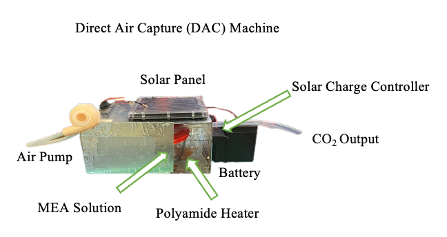
The Direct Air Capture (DAC) system was constructed using plexiglass panels wrapped in aluminum tape to form a 25.5 × 18 × 13 cm³ enclosure. Inside, a 500 mL glass container held 200 mL of a 30% aqueous MEA solution, with input and output tubing. The input tube was connected to a fan, while the output tube linked to the sodium-carbon dioxide (Na-CO₂) system. Due to time constraints, testing of the DAC was not conducted (Figure 1).

The DAC was designed to capture atmospheric CO₂ by bubbling air through the MEA solution, then releasing the captured CO₂ into the Na-CO₂ system via a polyimide heater.
The solar panel system was made with a 12 V, 1.7 W solar panel connected to a solar charge controller to regulate voltage for battery safety. A 12 V, 5 Ah battery was used. Integration of the battery and solar panel with the charge controller was followed by configuration of the output in parallel to power both the heating system and fan. An air pump, comprising a 9 V motor attached to a resin 3D-printed fan, was employed to inject air into the solution. The heating system consisted of a 75mm diameter polyimide heater affixed directly beneath the glass container to heat the solution. Separate switches, operating in parallel, controlled the fan and heater.
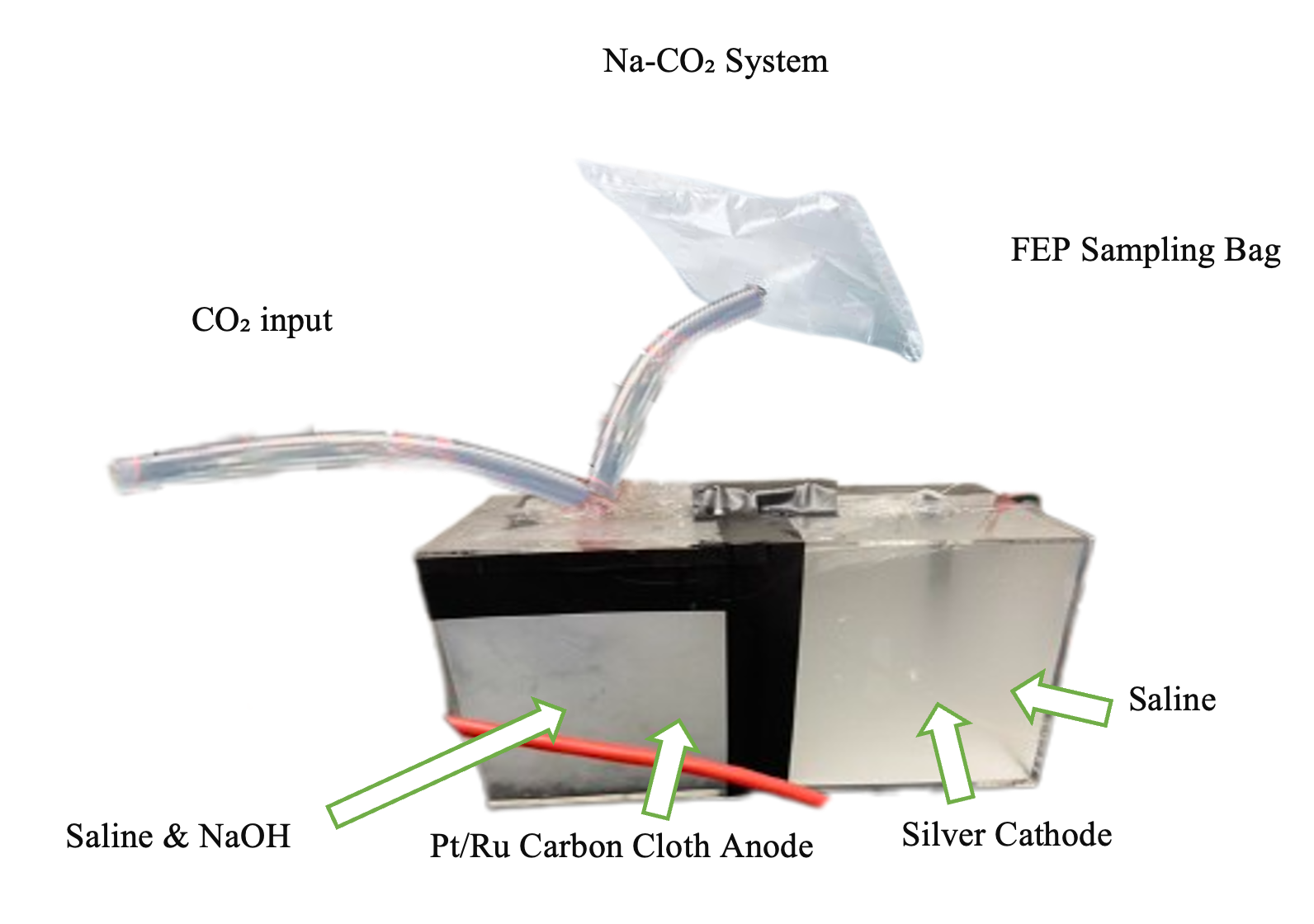
In regard to the Na-CO₂ system, cost efficiency was prioritized by using saline and sodium hydroxide as the power source. Two 500 ml clear plastic cubical containers, designated as Box 1 and Box 2, were joined with electrical adhesive tape. Box 1 was filled with 400 ml of saline, while Box 2 contained 200 ml of saline and 200 ml of 0.1 M NaOH. Holes were made in both boxes to accommodate a Na-ion graphite transporter and for various connections. Box 1 housed the cathode, while Box 2 featured additional holes for CO₂ supply from a CO₂ gas tank, anode placement, and gas release. The cathode was made using a graphite pole, while the anode comprised of carbon cloth housing a platinum/ruthenium (Pt/Ru) sheet. Silver wires were utilized to connect the anode and cathode to promote electron transfer (Figure 2).

To analyze the production of hydrogen and power by the device, the Na-CO₂ system was placed under a fume hood. A fluorinated ethylene propylene (FEP) gas sampling bag was connected to the collection tube. next to the anode. Additionally, the CO₂ was pumped into the saline and NaOH solution. Both the anode and cathode were attached to a voltmeter to measure current and voltage. Gas Chromatography (GC) was used to determine the concentration of the gas collected in the FEP gas sampling bag.
RESULTS.
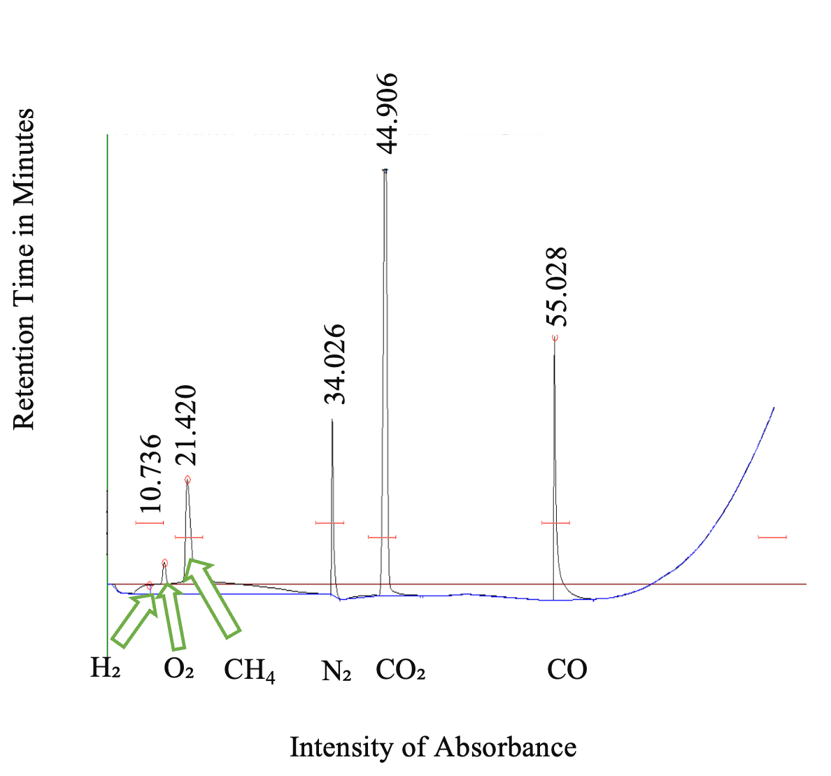
As per GC, the majority of gas in the sampling bag was CO₂ (77%), while only 4% was hydrogen. GC indicated that oxygen (O2), nitrogen (N2), methane (CH4), and carbon monoxide (CO) were also present in the FEP gas sampling bag (Figure 3).

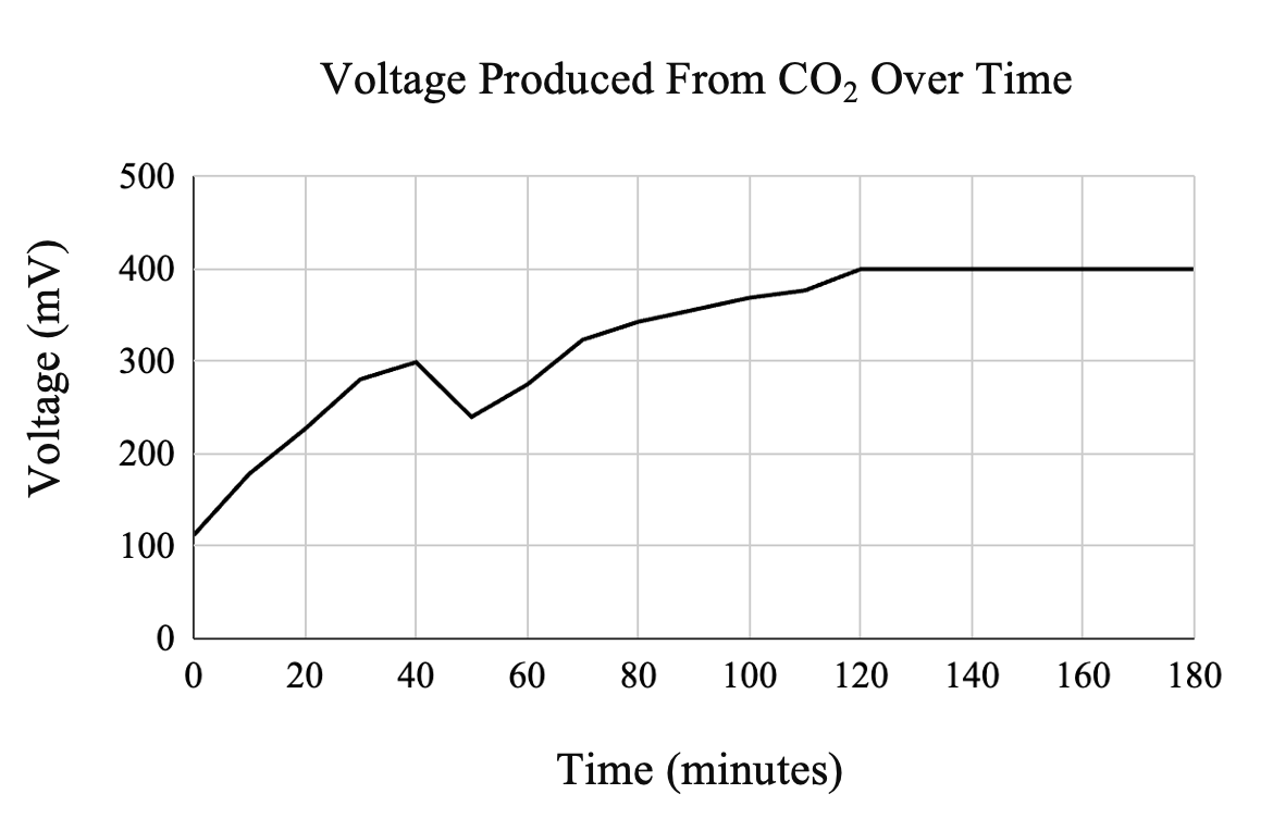
Voltmeter readings indicated that, in over two hours, the device generated a maximum voltage of 402 mV while the maximum amperage was 0.2 mA. This means that the system generated power of 0.0804 W (Figure 4).

DISCUSSION.
The goal of this project was to build a system that could effectively capture CO₂ from the atmosphere and convert it into electricity. Although the DAC was not used for this study due to time constraints, various reports vouch for the 30% MEA solution as a promising compound for carbon trapping [9-11]. As demonstrated in Figure 4, as concentrated CO₂ is introduced into the Na-CO₂ system, both electricity and hydrogen are produced. As suggested by Kim et al., optimizing the CO₂ flow rate is crucial for improving efficiency, with the ideal rate being 50 mL/min. Downregulating the CO₂ flow rate will increase the concentration of hydrogen produced, which is key for improving system performance. Higher hydrogen concentrations would make it more suitable for use in hydrogen fuel cells, where the hydrogen could be efficiently converted to electricity. By fine-tuning the CO₂ flow rate, the system’s output could be optimized, resulting in a greater amount of energy generation from the fuel cells. This optimization would ultimately enhance the system’s potential as a sustainable source of electricity.
A notable observation during the experiment was the drop in voltage at approximately 50 minutes, as shown in Figure 4. This decrease in voltage suggests a decline in the system’s efficiency over time. One possible explanation for this drop is electrode polarization, where the accumulation of reaction byproducts on the electrode surfaces increased internal resistance and hindered electron flow. Another contributing factor could be CO₂ oversaturation in the electrolyte, which might have disrupted ion transport and limited charge transfer. Additionally, electrolyte depletion over time may have reduced the availability of reactants necessary to sustain a stable voltage output. Addressing these issues by optimizing CO₂ flow rates, modifying electrode materials, and periodically refreshing the electrolyte could help improve the system’s long-term performance and maintain a steady voltage output.
Another key observation was the inflation of the FEP gas sampling bag during voltage and amperage measurements. This inflation indicates that gas production was continuous throughout the experiment, with CO₂ and hydrogen being released as byproducts of the reaction. The expansion of the bag suggests that the system was producing more gas than was being consumed in the electrochemical process. Since the voltage remained relatively stable before the drop at 50 minutes, it is likely that the accumulation of unreacted CO₂ did not immediately impact electrical performance. However, the presence of such a high percentage of unreacted CO₂ in the gas sample highlights the need for a more controlled and regulated CO₂ supply. Future adjustments, such as incorporating a flow regulator, could improve the efficiency of gas utilization and increase hydrogen yield.
This project faced two major challenges: time constraints and budget limitations. The construction of the DAC and Na-CO₂ system took approximately two months, which limited the opportunity for additional testing and system refinement. The system’s initial cost was $2,000, which exceeded the $300 budget. To stay within budget, several modifications were made to reduce costs while maintaining functionality. The NASICON membrane, a common solid electrolyte in sodium-based electrochemical systems, was replaced with graphite, which significantly lowered material expenses. Additionally, the cathode composition was altered by substituting platinum/carbon + iridium oxide in carbon cloth with a platinum/ruthenium alternative. These changes allowed for the system to be built within budget constraints while still achieving the goal of generating electricity and hydrogen. Although these modifications reduced costs, they may have also affected system performance, highlighting the need for further research into cost-effective yet efficient alternatives.
Future research should focus on optimizing CO₂ flow rates to increase hydrogen production while reducing excess CO₂ in the gas sample. This would help improve the overall efficiency of the system and enhance its viability as a renewable energy solution. Additionally, further improvements to the electrode materials and system design could help prevent voltage drops and sustain a more consistent power output over extended periods of operation. Enhancing the DAC system to ensure a continuous, regulated supply of CO₂ would also be critical for maximizing electrochemical conversion efficiency. Beyond laboratory-scale testing, scaling up the system and evaluating its performance under real-world conditions would be essential for assessing its potential as a large-scale solution for carbon capture and renewable energy generation.
ACKNOWLEDGMENTS.
We would like to thank Kent State University for the research internship and funding for this project in the College of Aeronautics and Engineering.
REFRENCES.
- A. Sodiq et al., A review on progress made in direct air capture of CO₂. Environ. Technol. Innov. 29, 102991 (2023).
- Q. Li et al., A novel strategy for carbon capture and sequestration by RHLPD processing. Front. Energy Res. 3 (2016).
- P. C. Buotte, B. E. Law, W. J. Ripple, L. T. Berner, Carbon sequestration and biodiversity co‐benefits of preserving forests in the western United States. Ecol. Appl. 30 (2019).
- A. Vinca, J. Emmerling, M. Tavoni, Bearing the cost of stored carbon leakage. Front. Energy Res. 6 (2018).
- J. Stepanek, J. Syblik, S. Entler, Axial Sco. Energy Convers. Manag. 274, 116418 (2022).
- C. Kim et al., Efficient CO₂ utilization via a hybrid Na-CO₂ system based on CO₂ dissolution. iScience 9, 278–285 (2018).
- Y. Wen et al., Expanded graphite as superior anode for sodium-ion batteries. Nat. Commun. 5 (2014).
- V. Karol, P. Sharma, A. Singh, D. Goel, S. Kaur, Review of energy storage devices: Fuel cells, hydrogen storage fuel cells, rechargeable batteries, PV solar cells. ACS Symp. Ser., 1–15 (2024).
- N. Wang, D. Wang, A. K. Riekkola, X. Ji, MEA-based CO₂ capture: A study focuses on MEA concentrations and process parameters. Front. Energy Res. 11 (2023).
- S. H. Vinjarapu et al., Results from pilot-scale CO₂. Appl. Energy 355, 122193 (2024).
- M. Akram, K. Milkowski, J. Gibbins, M. Pourkashanian, Comparative energy and environmental performance of 40% and 30% monoethanolamine at Pact Pilot Plant. Int. J. Greenh. Gas Control 95, 102946 (2020).
Posted by buchanle on Wednesday, June 25, 2025 in May 2025.
Tags: carbon dioxide capture, direct air capture, fuel cell technology, hydrogen production

